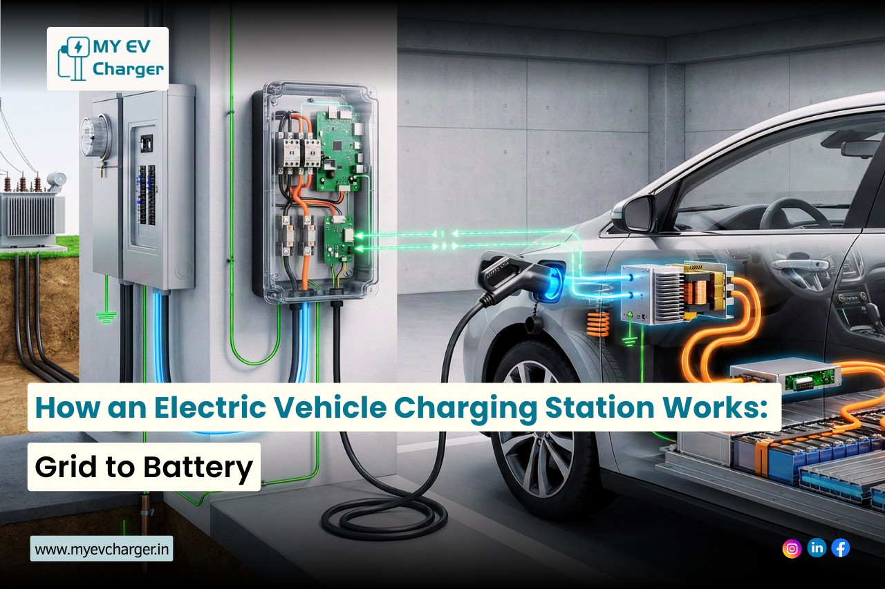

Electric vehicle charging stations efficiently deliver power from the grid to an EV’s battery through a controlled process involving EVSE (Electric Vehicle Supply Equipment), metering systems, and comprehensive safety protocols. This technical breakdown explores the complete power flow and key components that enable safe, reliable operation of modern EV charging stations, from utility connection through final battery charging.
Power Flow Overview: From Grid to Battery
The power journey in an electric vehicle charging station begins at the utility grid, typically delivering three-phase AC power at voltages up to 480V for commercial installations. This electricity flows through a dedicated service panel equipped with appropriately rated circuit breakers that provide the first level of overcurrent protection. The power then reaches the EVSE, which conditions and regulates voltage and current before delivering it to the vehicle through standardized connectors including J1772, CCS (Combined Charging System), or CHAdeMO.
For Level 2 AC charging—the most common configuration in public vehicle charging stations—the vehicle’s onboard charger performs AC-to-DC conversion, transforming the incoming alternating current into the direct current required by the battery. In contrast, DC fast chargers handle power conversion externally within the charging station itself, enabling dramatically higher power delivery speeds up to 350 kW or more, which can add 200+ miles of range in just 15-20 minutes.
Grid Connection and Power Distribution Architecture
Electrical Service Entry and Transformer Configuration
EV charging stations connect to the utility grid via dedicated transformers that step down high-voltage distribution lines to usable service voltages. Residential Level 2 charging stations typically use single-phase 240V service, while commercial and DC fast charging installations require three-phase power at 208V, 480V, or higher. The transformer capacity must accommodate not only the peak load of all charging stations but also account for simultaneous usage patterns and power quality requirements.
Power quality monitors integrated at the service entry continuously detect harmonics, voltage sags, swells, and transients before they impact charging delivery. These systems measure total harmonic distortion (THD), voltage imbalance, and frequency stability, ensuring the incoming power meets IEEE 519 standards for compatibility with sensitive power electronics. When grid disturbances occur, the monitoring system can trigger protective measures including temporary load reduction or charging suspension.
Circuit Protection and Load Management
Each charging station connects through dedicated circuit protection with appropriately sized breakers rated to handle maximum continuous current plus a safety margin. For example, a Level 2 charging station delivering 40A continuous requires a minimum 50A circuit breaker per National Electrical Code (NEC) requirements. This 125% safety factor prevents nuisance tripping while providing reliable protection against sustained overloads.
Advanced load management software prevents facility electrical systems from exceeding capacity limits by dynamically throttling multiple chargers based on real-time demand. These systems continuously monitor total facility load, available capacity, and individual charging station requirements. When approaching capacity limits, the load manager reduces power to lower-priority charging sessions or distributes available power equitably across all active stations, ensuring no circuit breakers trip while maximizing overall charging throughput.
The Role of EVSE: Intelligent Power Management
The Electric Vehicle Supply Equipment (EVSE) serves as the intelligent brain of every electric vehicle charging station, orchestrating all aspects of the charging process from initial connection through session completion. The EVSE controller manages bidirectional communication with the vehicle using Control Pilot and Proximity Pilot signals as defined by IEC 61851 international standards.
Power Negotiation and Control Pilot Signaling
When a vehicle connects to a charging station, the EVSE initiates communication through a 1 kHz square wave Control Pilot signal on a dedicated pin in the connector. The duty cycle of this PWM (pulse-width modulated) signal encodes the maximum available charging current. For example, in Mode 3 charging (the standard for modern EV charging stations), a 32A per phase capacity is communicated through a specific duty cycle percentage.
The vehicle responds by connecting a resistor network across the Control Pilot circuit, which changes the signal’s voltage level to indicate vehicle presence and readiness to charge. The EVSE continuously monitors this signal, detecting six distinct voltage states that represent different connection conditions: unplugged, vehicle detected but not ready, ready to charge, charging with ventilation required, charging in progress, and fault detected.
Dynamic Power Adjustment and State Machine Logic
The EVSE dynamically adjusts power output based on multiple real-time factors: grid voltage fluctuations, available facility capacity from load management systems, battery state of charge from vehicle communication, and thermal conditions in cables and connectors. This continuous adjustment optimizes charging speed while maintaining safety margins.
State machine logic enforces strict safety rules throughout the charging process. The EVSE includes power relays or solid-state contactors that physically enable or disable current flow. No energy transfers until the EVSE verifies a secure physical connection through Proximity Pilot detection, confirms proper ground continuity, validates insulation resistance, and receives explicit charge authorization from the vehicle. Any fault condition—such as poor connector seating, ground loss, or Pilot signal degradation—immediately triggers the state machine to open the power relays and cease charging.
Metering Process: Precision Energy Tracking
Smart metering systems in EV charging stations provide real-time energy tracking using precision current transformers (CTs) and voltage sensors that measure power flow in both directions. This bidirectional kWh measurement capability becomes critical for vehicle-to-grid (V2G) applications where energy can flow from vehicle batteries back to the facility or utility grid during peak demand periods.
Revenue-Grade Accuracy and Standards Compliance
Accuracy is paramount—commercial charging station meters must comply with ANSI C12.20 Class 0.5 or Class 0.2 standards, ensuring measurement accuracy within 0.5% or 0.2% respectively across the entire operating range. These revenue-grade meters undergo regular calibration and certification to maintain legal metrology standards required for commercial billing.
The metering system logs comprehensive session data from initial handshake to final disconnect: total energy delivered (kWh), session duration, peak power demand (kW), power factor, voltage and current profiles, and any interruptions or anomalies. This granular data enables precise cost allocation, demand charge optimization, and grid services billing.
Integration with Billing and Grid Services
Metering data supports multiple critical functions beyond simple billing. It enables sophisticated load balancing across charging station networks, provides utilities with accurate data for demand response programs, and facilitates participation in grid ancillary services markets. Many charging stations integrate with OCPP (Open Charge Point Protocol) for standardized remote monitoring, allowing network operators to access real-time metering data, configure billing parameters, and track utilization patterns across entire charging networks from centralized management platforms.
Comprehensive Safety Mechanisms and Protection Systems
Safety forms the foundation of every electric vehicle charging station design, with multiple redundant protection layers ensuring personnel safety and equipment preservation under all conditions, including fault scenarios.
Ground Fault Detection and Residual Current Protection
Ground fault protection begins with Residual Current Devices (RCDs) specifically designed for EV charging applications. Type A RCDs detect AC residual currents while Type B RCDs provide enhanced protection against DC fault currents that can occur in power electronics. These devices trip on leakage currents as low as 30mA AC or 6mA DC, well below levels that could cause human electrocution.
The RCD continuously compares current flow in the hot and neutral conductors (or all three phases in three-phase systems). Any imbalance exceeding the trip threshold indicates current leaking to ground—either through equipment insulation failure or a person in contact with an energized component. The RCD interrupts power within 40 milliseconds of detecting a fault, preventing sustained exposure to dangerous current.
For DC fast charging stations, isolation monitoring devices (IMDs) continuously measure insulation resistance between the high-voltage DC bus and ground. These specialized monitors detect insulation degradation before it becomes a safety hazard, typically triggering alerts when resistance drops below 100 ohms per volt of system voltage. For a 500V DC system, this equates to a minimum 50 kΩ insulation resistance threshold.
Thermal Monitoring and Overheat Protection
Temperature sensors strategically placed in cables and connectors provide continuous thermal monitoring, the most critical safety parameter for high-current charging. Charging connectors contain thermistors or RTDs (Resistance Temperature Detectors) embedded directly in the contact area where resistive heating is most pronounced.
When connector temperature exceeds safe thresholds—typically 90°C for warning and 110°C for immediate shutdown—the EVSE controller implements a graduated response. Initially, it reduces charging current to decrease resistive heating. If temperature continues rising despite current reduction, this indicates a high-resistance connection caused by contamination, corrosion, or mechanical damage. The controller then immediately halts charging and locks the connector until the fault is addressed, preventing potential fire hazards from thermal runaway.
Cable temperature monitoring extends throughout the charging cable length, with sensors at multiple points detecting overheating caused by excessive current, inadequate cooling, or physical damage. High-power DC charging cables often incorporate liquid cooling systems with flow and temperature sensors that verify proper cooling operation before allowing full-power charging.
Control Pilot Signal Monitoring and Fault Detection
Continuous Pilot signal monitoring provides real-time fault detection throughout the charging session. The EVSE controller samples the Pilot signal thousands of times per second, detecting anomalies that indicate connection problems, insulation failures, or communication errors.
Specific fault conditions detected through Pilot monitoring include: loss of vehicle connection (open circuit), short circuits to ground, diode check failures indicating damaged vehicle inlet, and invalid state transitions. Any detected fault immediately triggers the EVSE to open power relays and cease energy delivery within 50 milliseconds, preventing damage and safety hazards.
Mode 3 EVSE mandates continuous earthing verification before and during charging. The controller verifies that the protective earth conductor maintains continuity and low resistance (typically < 1 ohm) to the ground system. Loss of ground continuity—which could result from cable damage or connector wear—immediately halts charging, enforcing the principle that no power flows through insecure or ungrounded connections.
Overcurrent and Short Circuit Protection
Multiple layers of overcurrent protection safeguard against excessive current flow. The EVSE’s current sensors continuously monitor actual delivered current on each conductor. If measured current exceeds the negotiated charging current by more than 10% for longer than 100 milliseconds, the controller interprets this as a fault condition and opens the power contactors.
Short circuit protection operates on much faster timescales. Magnetic trip circuit breakers respond to short circuits within 5 milliseconds, interrupting potentially destructive fault currents before they can cause equipment damage or fire. DC fast chargers additionally employ electronic fuses or solid-state circuit breakers capable of interrupting DC faults in microseconds, protecting sensitive power electronics from damage.
Grid Integration and Vehicle-to-Grid Capability
Advanced EV charging stations enable bidirectional power flow, transforming electric vehicles from simple loads into distributed energy resources. Vehicle-to-grid (V2G) technology allows EVs to supply power back to the grid during peak demand periods, providing valuable grid services including frequency regulation, voltage support, and peak shaving.
Bidirectional Metering and Power Flow Control
V2G-capable charging stations require bidirectional power conversion electronics that can operate as both rectifiers (AC-to-DC for charging) and inverters (DC-to-AC for grid export). The power electronics must precisely synchronize with grid frequency and phase when exporting power, maintaining tight tolerances on voltage, frequency, and harmonics to meet IEEE 1547 interconnection standards.
Bidirectional metering tracks energy flow in both directions, essential for compensating vehicle owners for grid services provided. The metering system distinguishes between energy imported for charging and energy exported during V2G operation, applying appropriate tariffs or compensation rates to each transaction. Sophisticated rate structures may compensate V2G services at premium rates during critical peak periods or grid emergencies.
Smart Charging and Demand Response Integration
Load management software coordinates multiple charging stations to optimize facility power consumption while maximizing charging throughput. These systems implement various optimization strategies including time-of-use rate optimization, renewable energy prioritization, and demand charge minimization.
During demand response events, charging stations can automatically curtail load based on signals from utilities or grid operators. This capability enables charging station networks to participate in ancillary services markets, generating revenue while supporting grid stability. Advanced implementations use predictive algorithms that learn vehicle usage patterns, ensuring vehicles reach required charge levels despite temporary charging reductions during demand response periods.
Level 2 AC Charging: Onboard Power Conversion
Level 2 charging stations deliver AC power directly to the vehicle, relying on the vehicle’s onboard charger (OBC) for AC-to-DC power conversion. This architecture keeps the charging station relatively simple and cost-effective, with complexity shifted to the vehicle where it can be optimized for the specific battery chemistry and architecture.
Onboard Charger Architecture and Operation
The EVSE supplies standard 240V AC single-phase power at currents ranging from 16A to 80A (most commonly 32A-40A for consumer vehicles). This AC power travels through the J1772 charging cable to the vehicle’s onboard charger, which performs multiple power conversion stages:
First, an AC-DC rectifier converts alternating current to direct current using diode bridges or active rectification with MOSFETs. Second, a Power Factor Correction (PFC) stage boosts the DC voltage to 400-450V while ensuring the charger draws current in phase with voltage, achieving power factors above 0.99 and minimizing harmonic distortion injected back to the grid. Finally, an isolated DC-DC converter provides galvanic isolation between grid and battery while precisely regulating output voltage and current to match battery requirements throughout the charging cycle.
Charging Power Negotiation via Control Pilot
Power negotiation occurs through the J1772 Control Pilot signal, a 1 kHz square wave with duty cycle encoding maximum available current. The relationship follows: Imax = (duty_cycle × 0.6) amperes for duty cycles 10%-85%. For example, a 50% duty cycle indicates 30A maximum available current.
The vehicle’s onboard charger responds by drawing only the current it can safely process, which may be less than the station’s maximum based on battery temperature, state of charge, cell balancing requirements, and thermal management capacity. This dynamic negotiation ensures optimal charging rates while preventing battery damage from excessive power during temperature extremes or near full charge.
DC Fast Charging: High-Power External Conversion
DC fast charging represents a fundamental architectural shift, moving power conversion from vehicle to charging station. This enables dramatically higher power levels—50 kW to 350 kW or more—impossible with onboard chargers due to weight, space, and cooling constraints.
Three-Phase Rectification and Active Front End
DC fast chargers accept three-phase AC input at 480V (North America) or 400V (Europe), converting it through active rectifiers employing IGBT or silicon carbide (SiC) power modules. These active front-end rectifiers provide multiple advantages over traditional passive diode bridges:
Power factor exceeding 0.99 across the entire operating range, minimizing reactive power and utility penalties. Total Harmonic Distortion (THD) below 5%, meeting IEEE 519 grid compatibility standards. Bidirectional power flow capability enabling V2G operation. Conversion efficiency exceeding 96%, reducing operating costs and cooling requirements.
Wide-Range DC-DC Conversion
Following rectification, the DC voltage feeds a high-power DC-DC converter that regulates output across a wide voltage range, typically 150V to 1000V DC, accommodating diverse vehicle battery architectures. Modern EVs use battery voltages ranging from ~350V (Nissan Leaf) to 800V+ (Porsche Taycan, Hyundai Ioniq 5), requiring converters with extensive operating ranges.
The DC-DC stage continuously adjusts voltage and current based on real-time CAN bus communication with the vehicle’s Battery Management System. This communication occurs at 100-500 Hz update rates, enabling precise tracking of battery requirements as they evolve during the charging session. The converter implements constant current (CC) mode during bulk charging and constant voltage (CV) mode during the final phase, following the battery’s CC-CV charging profile.
Liquid Cooling and Thermal Management
A 350 kW DC fast charger operating at 96% efficiency still dissipates 14 kW as waste heat—equivalent to seven residential space heaters running continuously. This enormous thermal load demands sophisticated liquid cooling systems with forced circulation, heat exchangers, and temperature control.
The cooling system typically uses water-glycol coolant circulating through cold plates thermally bonded to power semiconductors, inductors, and DC bus capacitors. Temperature sensors throughout the cooling loop monitor coolant temperature, with thermal management controllers modulating pump speed and fan operation to maintain power electronics below maximum junction temperatures (typically 125°C for IGBTs, 175°C for SiC).
The highest-power DC chargers extend liquid cooling into the charging cable itself, cooling conductors and connector contacts. This cable cooling enables sustained 350+ kW power delivery using cables that remain cool and flexible despite carrying 500+ amperes continuously.
Advanced Communication Protocols
ISO 15118: Plug & Charge Automation
The ISO 15118 standard revolutionizes EV charging by enabling automated authentication, authorization, and billing without any user intervention. When an ISO 15118-compatible vehicle connects to a compliant charging station:
The vehicle and station establish an encrypted communication channel over the charging cable using High-Level Communication (HLC) through power line carrier technology or dedicated communication pins. The vehicle transmits its unique identification certificate and payment credentials secured with PKI (Public Key Infrastructure) cryptography. The charging station verifies authorization by communicating with backend payment systems and certificate authorities. Charging begins automatically within seconds of connection—no RFID cards, credit cards, or mobile apps required.
Beyond Plug & Charge convenience, ISO 15118 enables advanced smart charging features: Dynamic pricing communication where the vehicle receives real-time electricity prices and adjusts charging to minimize cost. Renewable energy prioritization where charging rates increase when solar or wind generation peaks. Bidirectional power flow coordination for V2G and V2H (vehicle-to-home) applications.
Battery Management System Integration
The vehicle’s Battery Management System (BMS) maintains ultimate authority over charging throughout the session. The BMS continuously monitors and controls:
Individual cell voltages across all battery modules, ensuring no cell exceeds maximum voltage (typically 4.2V for lithium-ion). Cell and module temperatures measured by dozens of thermistors, preventing thermal damage. State of Charge (SoC) calculated through coulomb counting and voltage correlation. Pack current and power enforcing maximum rates based on temperature and SoC. Isolation resistance verifying high-voltage system integrity.
The BMS calculates maximum safe charging power in real-time, typically updating this value every 100-500 milliseconds. If any parameter approaches unsafe limits—cell overvoltage, excessive temperature, or isolation degradation—the BMS immediately requests reduced power or charging termination through the communication protocol. This hierarchical control ensures battery safety regardless of charging station behavior.
Network Management and OCPP Integration
Modern EV charging stations maintain persistent network connectivity enabling remote management, monitoring, and control. Connectivity methods include 4G/5G cellular modems, Wi-Fi, or Ethernet, with cellular providing the most reliable option for outdoor installations without existing network infrastructure.
Open Charge Point Protocol (OCPP) Standard
OCPP has emerged as the universal standard for charging station management, defining WebSocket-based communication between charging stations and central management systems. OCPP 1.6 and 2.0.1 specify standardized JSON messages for all operational aspects:
Transaction management: remotely starting and stopping charging sessions, authorizing users, and processing RFID tags. Configuration and diagnostics: reading and writing charging station parameters, retrieving logs, and uploading diagnostic data. Firmware updates: over-the-air software deployment enabling bug fixes and feature additions without site visits. Smart charging coordination: sending charging profiles that specify maximum power as a function of time, enabling sophisticated load management and demand response.
OCPP standardization enables interoperability between charging stations from different manufacturers and management platforms from multiple vendors, preventing vendor lock-in. Fleet operators can manage mixed charging station fleets through a single interface, while station owners can switch management platforms without replacing hardware.
Critical Components Summary
The following table summarizes the key components, their functions, and safety features in modern electric vehicle charging stations:
| Component | Primary Function | Key Safety Features |
| EVSE Controller | Power negotiation, communication management, session control via Control Pilot and Proximity Pilot signals | Pilot signal fault detection, state machine enforcement, relay control, continuous monitoring |
| Smart Meter | Bidirectional energy tracking, billing data collection, load management support | Real-time anomaly alerts, ANSI C12.20 accuracy compliance, session logging |
| RCD (Type B) | Ground fault and leakage current protection for AC and DC faults | Trips on 6mA DC or 30mA AC leakage, <40ms response time |
| Cable Thermal Sensors | Continuous temperature monitoring of conductors and connectors | Auto-shutdown on overheat (>110°C), graduated current reduction at 90°C |
| Power Electronics | AC-DC rectification, DC-DC conversion, voltage/current regulation | Overvoltage/undervoltage protection, short circuit detection, isolation monitoring |
| Communication Interface | Vehicle-station data exchange via CAN, PLC, or ISO 15118; backend connectivity via OCPP | Encrypted communications, authentication, real-time BMS integration |
| Load Management System | Dynamic power allocation across multiple stations, demand response coordination | Circuit overload prevention, real-time capacity monitoring, graceful degradation |
Conclusion: Integrated Safety and Efficiency
Electric vehicle charging stations represent sophisticated integration of power electronics, communication protocols, metering systems, and comprehensive safety mechanisms. From the initial grid connection through final battery charging, multiple layers of protection and intelligent control work seamlessly to deliver reliable, safe charging experiences.
The EVSE controller orchestrates this complex system, managing power negotiation via Control Pilot signals, enforcing safety interlocks, and coordinating with vehicle Battery Management Systems. Metering systems provide revenue-grade accuracy compliant with ANSI C12.20 standards, enabling precise billing and grid integration. Safety mechanisms including RCD ground fault protection, thermal monitoring, and continuous Pilot signal verification ensure personnel safety and equipment preservation under all conditions.
As EV adoption accelerates, charging infrastructure continues evolving toward higher power levels, bidirectional V2G capability, and enhanced smart grid integration. Technologies like ISO 15118 Plug & Charge, OCPP-based network management, and megawatt-scale charging promise to make vehicle charging stations even more convenient, intelligent, and integral to the future electrical grid. The technical sophistication hidden behind the simple act of plugging in a vehicle enables the practical electric mobility that will define transportation for decades to come.